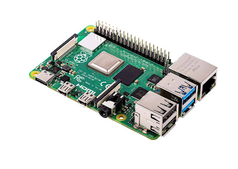
Raspberry Pi 4 Device Tree compile and setup; Serial Port UARTS 2,3,4,5 ; IC2 : SPI
Raspberry Pi 4 Device Tree compile and setup
My AIM is too add a Serial Port 3 UART Device Tree Overlay for a Adafruit.com GPS device
https://forums.raspberrypi.com/viewtopic.php?t=244827 DT Overlay enable 5 serial ports;
https://learn.adafruit.com/adafruit-ultimate-gps/overview
We carry a few different GPS modules here in the Adafruit shop, but none that satisfied our every desire - that's why we designed this little GPS breakout board. We believe this is the Ultimate GPS module, so we named it that. It's got everything you want and more:
https://www.adafruit.com/product/790
Description
For those who want to integrate our awesome Ultimate GPS module into their own projects, we now have the raw sub-module available. Don't be fooled by it's small size, this is a very sensitive, high quality GPS module with all the extras you could want and more at under 6 grams!
As of October 12, 2022 - the original "Ultimate GPS" module we used was discontinued by the vendor. We found and are using a nearly-identical module with the same functionality. The commands for querying the antenna have changed slightly so existing projects may need to update their firmware if they do antenna status stuff - general NMEA commands and sentences are the same.
https://www.adafruit.com/product/4279
Adafruit Ultimate GPS
https://learn.adafruit.com/adafruit-ultimate-gps/circuitpython-parsing Circuit Python Serial parsing
https://blog.stabel.family/raspberry-pi-4-device-tree/
What is the Device Tree?
Roughly speaking the Device Tree describes all the hardware of a device in a tree format. It is especially used for anything that can't be discovered automatically like serial interfaces, internal memory, oscillators, ... (in contrast to e.g. USB or PCI devices). As the Raspberry Pi has a lot of GPIO headers exposed, additional devices can be added that the current device tree doesn't know about. That's where overlays come into play.
https://pi4j.com/getting-started/understanding-the-pins/
Really good description and documentation of I2C and SPI pins on the Raspberry Pi 4B.
Below is a serial port tutroial from Raspberry Pi to Arduino
https://roboticsbackend.com/raspberry-pi-arduino-serial-communication/
Device Tree Overlays
https://drive.google.com/file/d/0B8gkYppHOJNMTlZ1NWZJazFRYW8/view?resourcekey=0-YiwRMZhIUzrwiqPp7KoTnw File cmdline.txt 126 bytes, config.txt 4K bytes
Their source code is at https://github.com/raspberrypi/linux/tree/rpi-5.4.y/arch/arm/boot/dts/overlays/. The compiled files (They can be converted back to source using dtc) are att /boot/overlays.
Readme file on Device Tree Overlays
https://raw.githubusercontent.com/raspberrypi/firmware/master/boot/overlays/README
More Complete introduction to Device Tree Overlays is here:
http://www.raspberrypi.org/documentation/configuration/device-tree.md
https://raspberrypi.stackexchange.com/questions/45570/how-do-i-make-serial-work-on-the-raspberry-pi3-pizerow-pi4-or-later-models/107780#107780
Raspberry Pi4 UART
The BCM2711 used in the Raspberry Pi 4 Model B, the Raspberry Pi 400, and the Raspberry Pi Compute Module 4 has 4 additional UART (uart2-uart5) in addition to uart0/1 on the older Pi (only one of which can be used as they share GPIO).
Functionally these are equivalent to the fully featured PL011 UART on uart0 and can optionally be configured with CTS/RTS. See UART configuration for Foundation documentation.
These can be enabled (by editing /boot/config.txt), but this requires careful consideration of the impact on GPIO functionality.
Activation of CTS/RTS functionality has additional impact.
NOTE you can enable overlays on the fly e.g
sudo dtoverlay uart4.
Manually loaded overlays can be removed e.gsudo dtoverlay -r uart4
- uart2 uses GPIO0/1 which are reserved1 and possibly impact on normal Raspbian functionality.
- uart3 uses GPIO4/5 which is OK, although GPIO4 is commonly used for other purposes.
- uart4 uses GPIO8/9 which are used for SPI0.
- uart5 uses GPIO12/13 which conflict with the default pin allocation of gpio-fan (although this can be changed).
1 These pins are documented as "RESERVED". It is possible to configure uart2 inconfig.txt(at least if no HATs are present). Impact on functionality is unknown.
If additional UARTs are enabled they will appear as /dev/ttyAMAn
The first will be /dev/ttyAMA1 and increment if additional UART are enabled.
Name:   uart0
Info:   Change the pin usage of uart0
Load:   dtoverlay=uart0,<param>=<val>
Params: txd0_pin                GPIO pin for TXD0 (14, 32 or 36 - default 14)

        rxd0_pin                GPIO pin for RXD0 (15, 33 or 37 - default 15)

        pin_func                Alternative pin function - 4(Alt0) for 14&15,
                                7(Alt3) for 32&33, 6(Alt2) for 36&37


Name:   uart1
Info:   Change the pin usage of uart1
Load:   dtoverlay=uart1,<param>=<val>
Params: txd1_pin                GPIO pin for TXD1 (14, 32 or 40 - default 14)

        rxd1_pin                GPIO pin for RXD1 (15, 33 or 41 - default 15)


Name:   uart2
Info:   Enable uart 2 on GPIOs 0-3
Load:   dtoverlay=uart2,<param>
Params: ctsrts                  Enable CTS/RTS on GPIOs 2-3 (default off)


Name:   uart3
Info:   Enable uart 3 on GPIOs 4-7
Load:   dtoverlay=uart3,<param>
Params: ctsrts                  Enable CTS/RTS on GPIOs 6-7 (default off)


Name:   uart4
Info:   Enable uart 4 on GPIOs 8-11
Load:   dtoverlay=uart4,<param>
Params: ctsrts                  Enable CTS/RTS on GPIOs 10-11 (default off)


Name:   uart5
Info:   Enable uart 5 on GPIOs 12-15
Load:   dtoverlay=uart5,<param>
Params: ctsrts                  Enable CTS/RTS on GPIOs 14-15 (default off)
The following summarises the pin usage:-
        TXD RXD CTS RTS     Board Pins
uart0   14  15              8   10
uart1   14  15              8   10
uart2   0   1   2   3       27  28  (I2C0)
uart3   4   5   6   7       7   29
uart4   8   9   10  11      24  21  (SPI0)
uart5   12  13  14  15      32  33  (gpio-fan)
You CAN use uart2 on Pi4 but need to disable other uses of GPIO0/1 with force_eeprom_read=0 & disable_poe_fan=1
https://forums.raspberrypi.com//viewtopic.php?f=107&t=138223&start=50
https://hackaday.com/2022/02/01/did-you-know-that-the-raspberry-pi-4-has-more-spi-i2c-uart-ports/
Hackaday February 1, 2022 Raspberry Pi 4 has more spi I2c Uart ports
We’ve gotten used to the GPIO-available functions of Raspberry Pi computers remaining largely the same over the years, which is why it might have flown a little bit under the radar: the Raspberry Pi 4 has six SPI controllers, six I2C controllers, and six UARTs – all on its 40-pin header. You can’t make use of all of these at once, but with up to four different connections wired to a single pin you can carve out a pretty powerful combination of peripherals for your next robotics, automation or cat herding project.


Comments
Post a Comment